After you create a database, your next task is to create all tables belonging to it. As with database creation, you can create tables by using either Object Explorer or Transact-SQL. Again, only Object Explorer is discussed here.
To create a table using Object Explorer, expand the Databases folder, expand the database, right-click the Tables subfolder, and then click New Table.
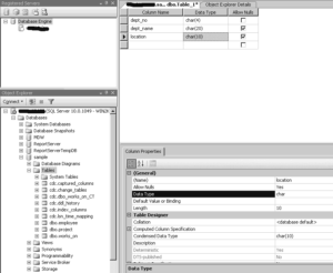
To demonstrate the creation of a table using Object Explorer, the department table of the sample database will be used as an example. Enter the names of all columns with their properties. Enter the column names, their data types, and the NULL property of each column in the two-dimensional matrix, as shown in the top-right pane of Figure 3-7.
All data types supported by the system can be displayed (and one of them selected) by clicking the arrow sign in the Data Type column (the arrow appears after the cell has been selected). Subsequently, you can type entries in the Length, Precision, and Scale rows for the chosen data type on the Column Properties tab (see the bottom-right pane of Figure 3-7). Some data types, such as CHAR, require a value for the Length row, and some, such as DECIMAL, require a value in the Precision and Scale rows. On the other hand, data types such as INTEGER do not need any of these entries to be specified. (The valid entries for a specified data type are highlighted in the list of all possible column properties.)

The check box in the Allow Nulls column must be checked if you want a table column to permit NULL values to be inserted into that column. Similarly, if there is a default value, it should be entered in the Default Value or Binding row of the Column Properties tab. (A default value is a value that will be inserted in a table column when there is no explicit value entered for it.)
The column dept_no is the primary key of the department table. (For the discussion of primary keys of the sample database, see “Database Design ,Normal Forms ,Entity-Relationship Model“.) To specify a column as the primary key of a table, you must right-click the column and choose Set Primary Key. Finally, click the × in the right pane with the information concerning the new table. After that, the system will display the Choose Name dialog box, where you can type the table name.
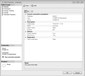
To view the properties of an existing table, double-click the folder of the database to which the table belongs, double-click Tables, and then right-click the name of the table and choose Properties. Figure 3-8 shows the Table Properties dialog box for the employee table.

To rename a table, right-click the name of the table in the Tables folder and choose Rename. To remove a table, right-click the name of the table in the Tables folder in the database to which the table belongs and select Delete.
After you have created all four tables of the sample database (employee, department, project, and works_on), you can use another feature of SQL Server Management Studio to display the corresponding entity-relationship (ER) diagram of the sample database. (The process of converting the existing tables of a database into the corresponding ER diagram is called reverse engineering.) To see the ER diagram of the sample database, right-click the Database Diagrams subfolder of the sample database and select New Database Diagram.
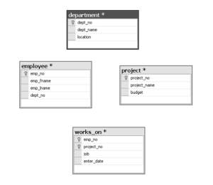
The first (and only) step is to select tables that will be added to the diagram. After adding all four tables of the sample database, the wizard completes the work and creates the diagram (see Figure 3-9).

The diagram shown in Figure 3-9 is not the final diagram of the sample database because, although it shows all four tables with their columns (and the corresponding primary keys), it does not show any relationship between the tables. A relationship between two tables is based on the primary key of one table and the (possible) corresponding column(s) of the other table.
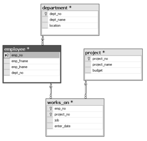
There are exactly three relationships between the existing tables of the sample database: first, the tables department and employee have a 1:N relationship, because for each value in the primary key column of the department table (dept_no), there is one or more corresponding values in the column dept_no of the employee table. Analogously, there is a relationship between the tables employee and works_on, because only those values that exist in the primary key of the employee table (emp_no) appear also in the column emp_no of the works_on table. The third relationship is between the tables project and works_on, because only values that exist in the primary key of the project table (pr_no) appear also in the pr_no column of the works_on table.
To create each of the three relationships described, you have to redesign the diagram with the column that corresponds to the primary key column of the other table. (Such a column is called a foreign key.) To see how to do this, use the employee table and define its column dept_no as the foreign key of the department table:
- Click the created diagram, right-click the graphical form of the employee table in the detail pane, and select Relationships. In the Foreign Key Relationships dialog box, click Add.
- In the dialog box, expand the Tables and Columns Specification column and click the … button.
- Select the table with the corresponding primary key (the department table).
- Choose the dept_no column of this table as the primary key and the column with the same name in the employee table as the foreign key and click OK. Click Close.
Figure 3-10 shows the modified diagram after all three relationships in the sample database have been created.

